emonDC
emonDC is a project aiming to develop DC current and voltage measuring tools compatible with openenergymonitor.org project.
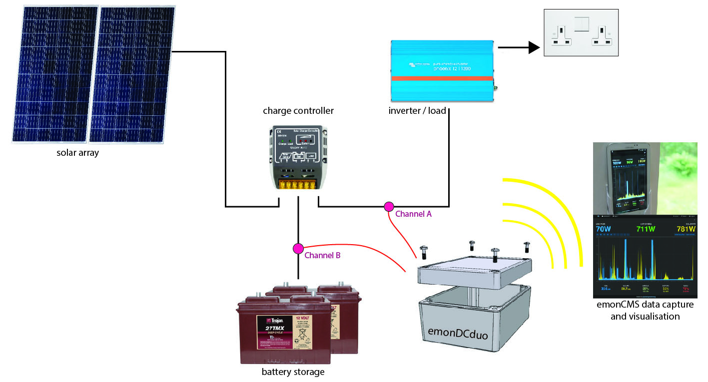
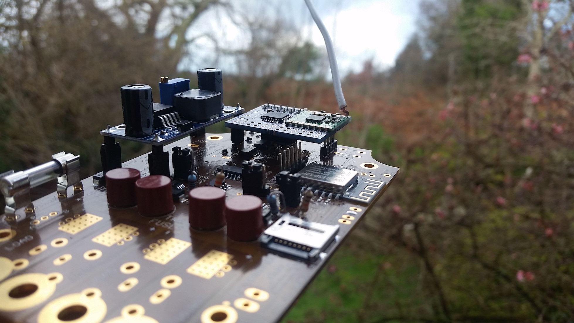
The main board in development is emonDCduo, a dual-channel generator/battery monitor, WiFi enabled, aimed at solar/battery systems.
Project status: Reviewing Project. Develoment Units not available.
https://shop.openenergymonitor.com/
Target Uses
- 12V, 24V and 48V Solar PV systems, up to 65V
- Battery monitoring.
- Remote DC datalogging.
Be safe. Extra-low voltages can still mean high currents.
Contents
- Target Uses
- Features
- Hardware Options
- Firmware
- Customisations
- Setup Guides
- Support
- Safety
- DC Monitoring Approaches
- Project Aims
- License
Features
Latest spec:
- Two-channel high only DC current and voltage sensing, up to 64.4V or 75V, suitable for a wide range of low-voltage generator/battery systems.
- 50Amps onboard shunt rating or 1000A external shunt rating.
- Hall-effect current sensor footprint alternative for isolated current only measurement.
- Waterproof, clear-top plastic case.
- 128 x 32 OLED display option.
- WiFi Connectivity.
- Low-power mode (10mA draw).
- Accurate 12-bit ADC.
- Over-voltage and reverse voltage protected (fuses).
Also:
- It can function as independent unit self-powered using an onboard buck regulator module, powered from either measurement channel. Data can be stored locally to a MicroSD card, keeping time with on-board RTC and coin-cell.
- Radio transmission of data possible through RFM69Pi module.
- Voltage divisions for reference voltages easily modified by soldering for maximum resolution for given system.
- The I2C port can connect control boards for power management, in development.
- Skipping wireless transmission, a physical cable UART connection is possible, compatible with RS485 pending testing.
![]()
Hardware Options
emonDCduo as designed here has shunt, termination, power-supply and other module options.
See this demo video of the options, listed below in detail.
The Shunt
Onboard @ 50Amps max || External @ 1000Amps max.
Onboard shunts should be selected to not dissipate more than 50% of their rated value continuously shunt power calculator.
Terminations for Onboard Shunts (up to 50Amps)
- For 10mm2 cable (50Amps approx). 10.16mm pitch Terminal Block, such as this.
- For 4mm2 cable (25Amps approx). 7.62mm pitch Terminal Block, such as this.
- For 6mm2 cable (35Amps approx). 5mm Ring Terminals bolted on. Ring terminal outer-diameter not exceeding 11.0mm.
- Directly soldered cable, using the bolt mounts.
Terminations for External Shunts
- Any of the above, 7.62mm pitch Terminal Block recommended.
- Example of external shunt (external link).
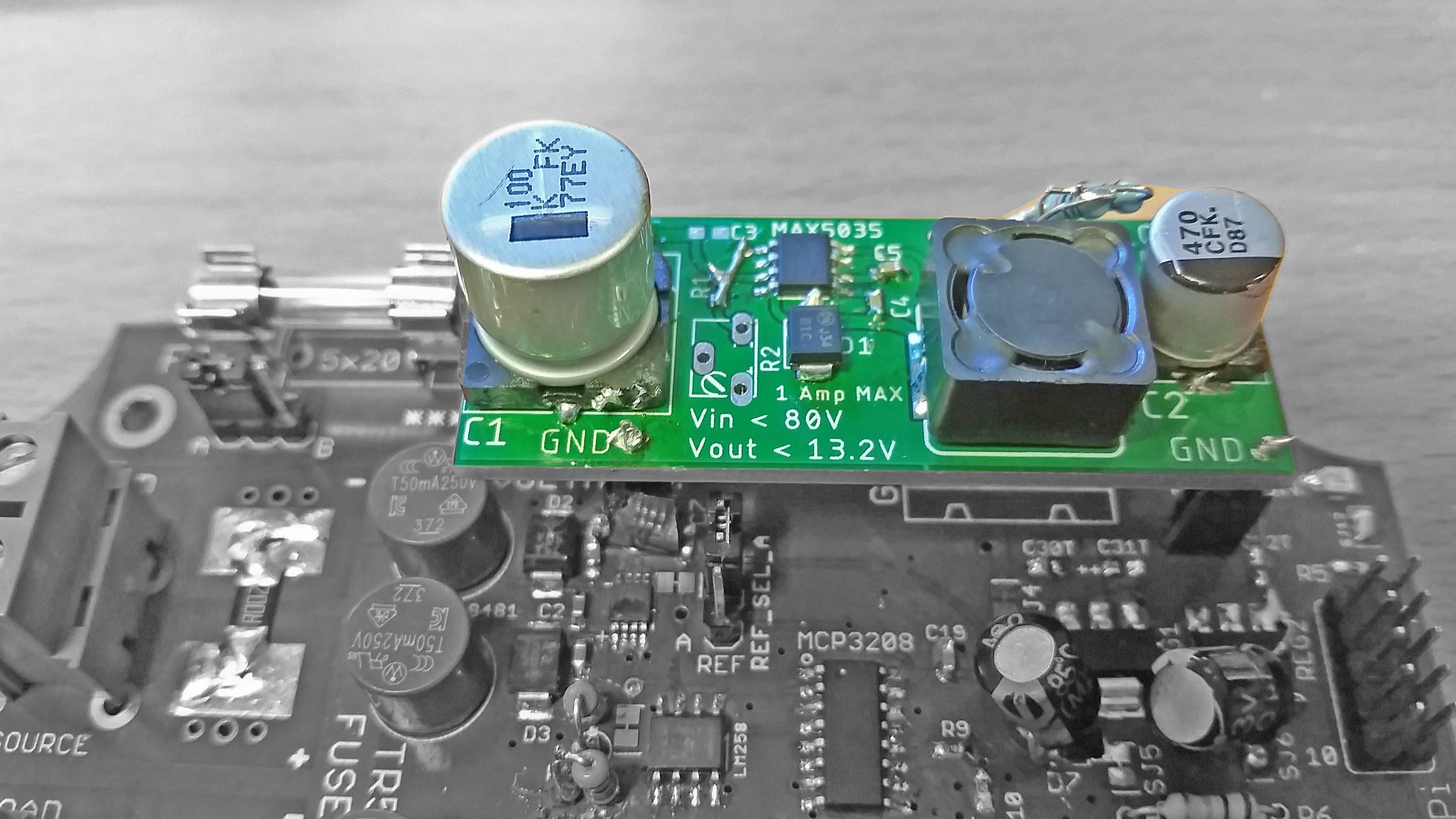
Power Supply Options
Using a buck regulator the board can be self-powered from either current sense channel.
-
My own DC-DC buck regulator featuring under-voltage lockout for battery protection, adjustable output voltage, rated at 3A for 10s or 1A continuous. note: using an onboard buck regulator is preceded by fuse F1.
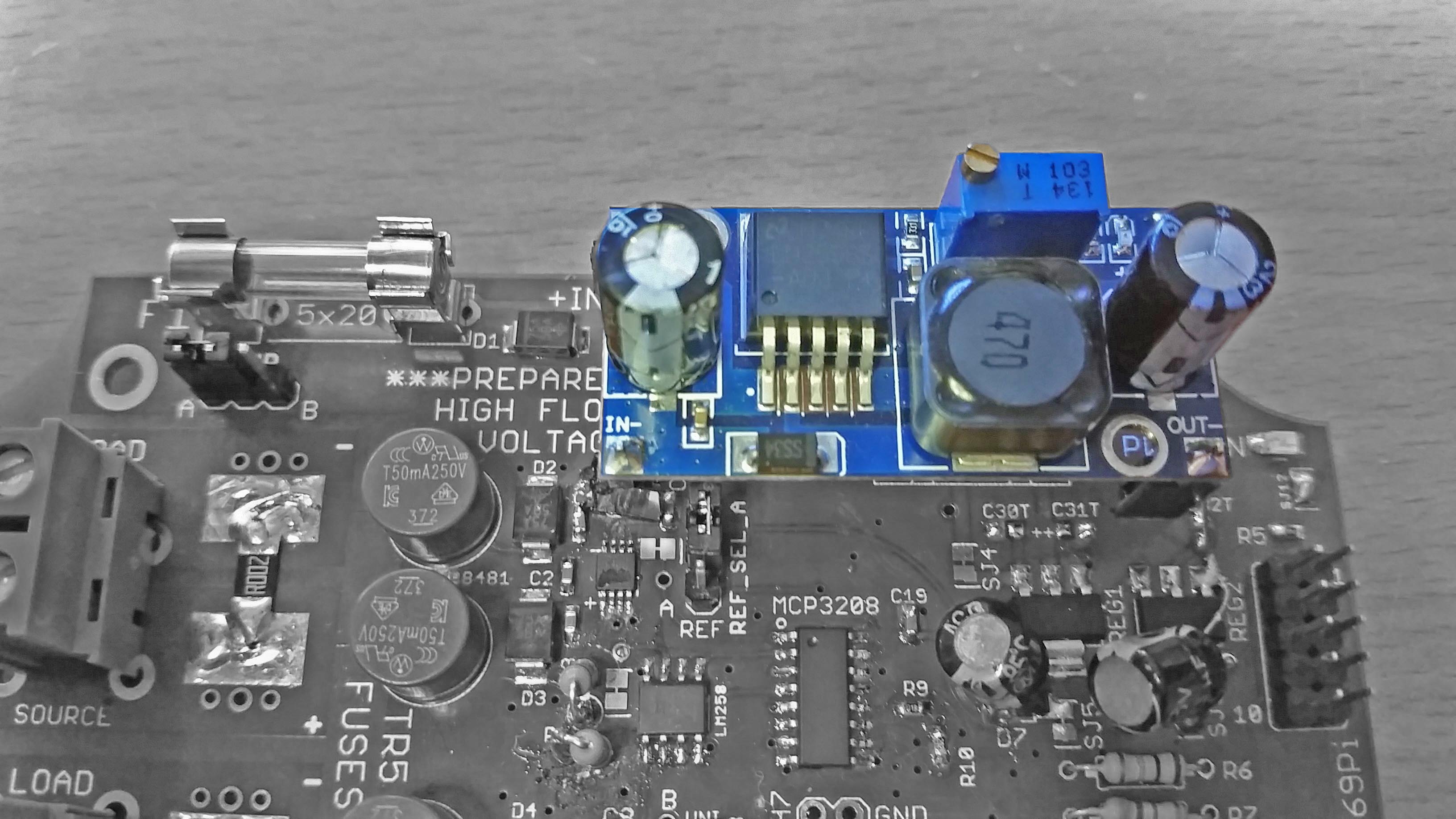
-
The LM2596 buck modules on ebay, shown here fitted. note: using an onboard buck regulator is preceded by fuse F1.
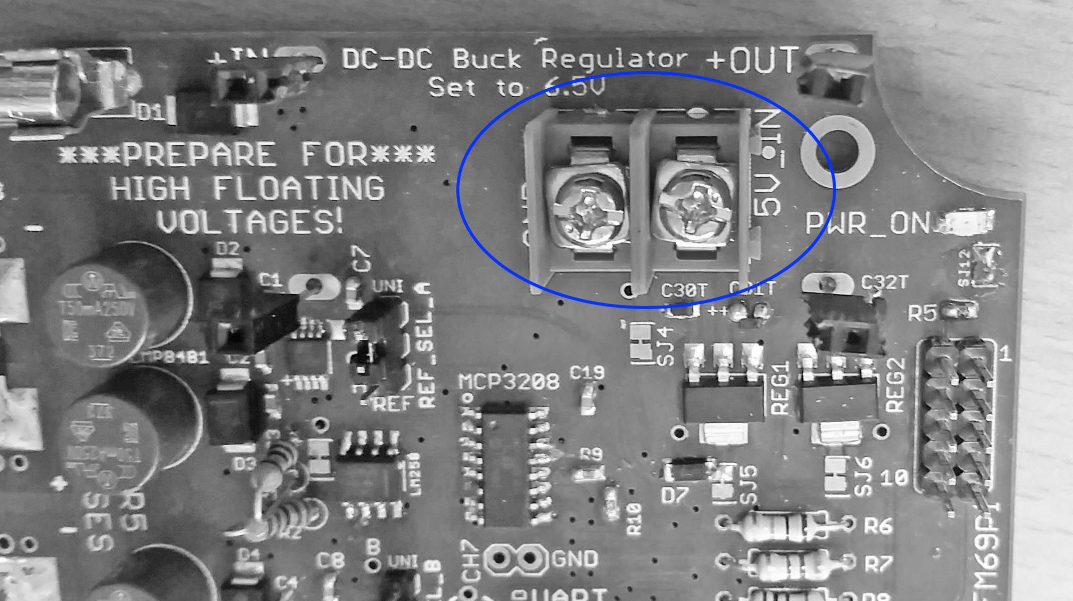
-
5V input with 5.08mm pitch Terminal Block for 5V direct input. I could not enable a USB connection for the safety reasons in floating-ground systems.
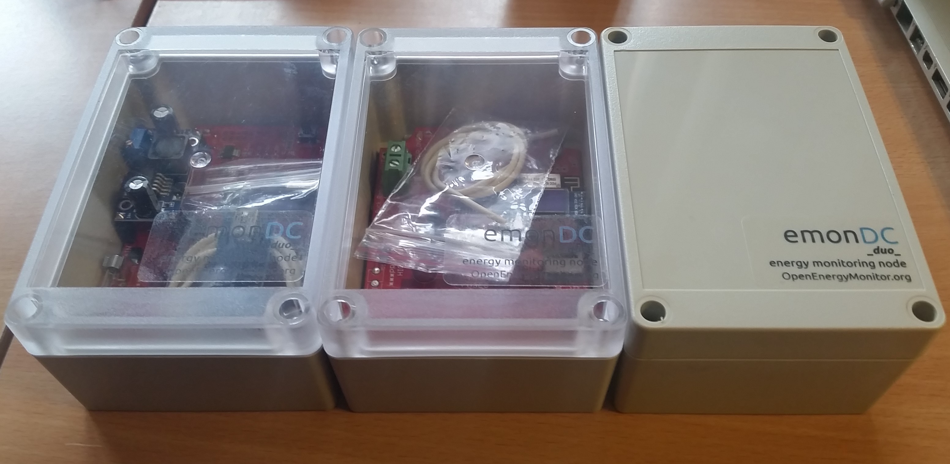
Enclosures
emonDCduo has been designed for waterproof plastic enclosures from Lincoln Binns.
Holes can be drilled easily, or prepared units can be bought from the OpenEnergyMonitor shop.
Module Options
I2C modules:
- 128x32 I2C OLED Display module cycles through real-time and daily data, including network information if connected.
- RTC based on PCF8523, with coin cell backup, parts sold as kit.
- Any I2C control module can be fitted in parallel. Search for ‘i2c io expander module board’ for some options, PCF8574 and PCF8575 based modules have been tested and work fine.
Other modules:
- RFM69Pi radio module from OpenEnergyMonitor, typically 433MHz.
The board sets sail with a RFM69Pi module
Firmware
Find firmware here:
https://github.com/danbates2/emonDC/tree/master/firmware
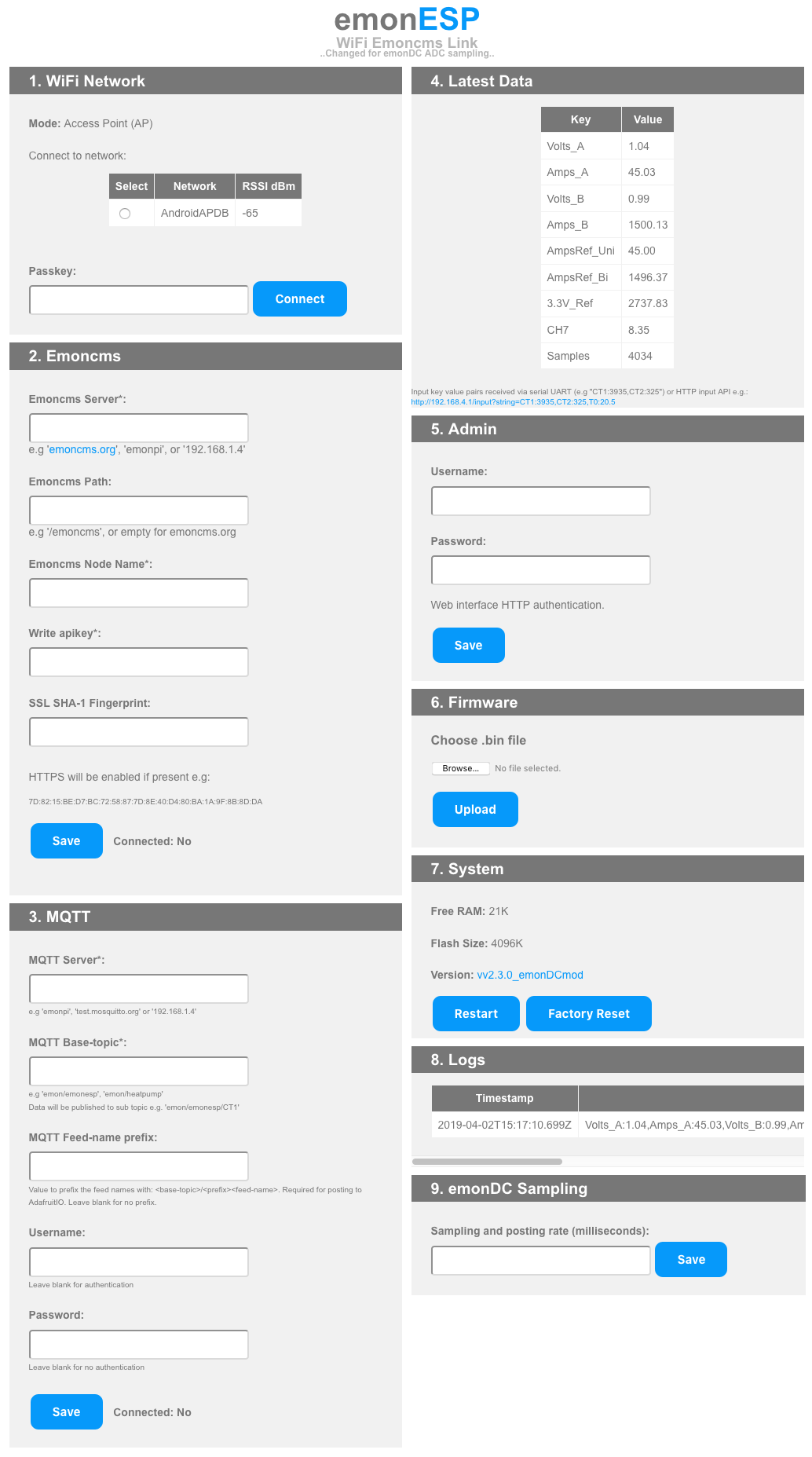
It is based on emonESP, and detailed instructions on compiling and uploading the firmware can be found in it’s documentation.
https://github.com/openenergymonitor/EmonESP
Other Customisation
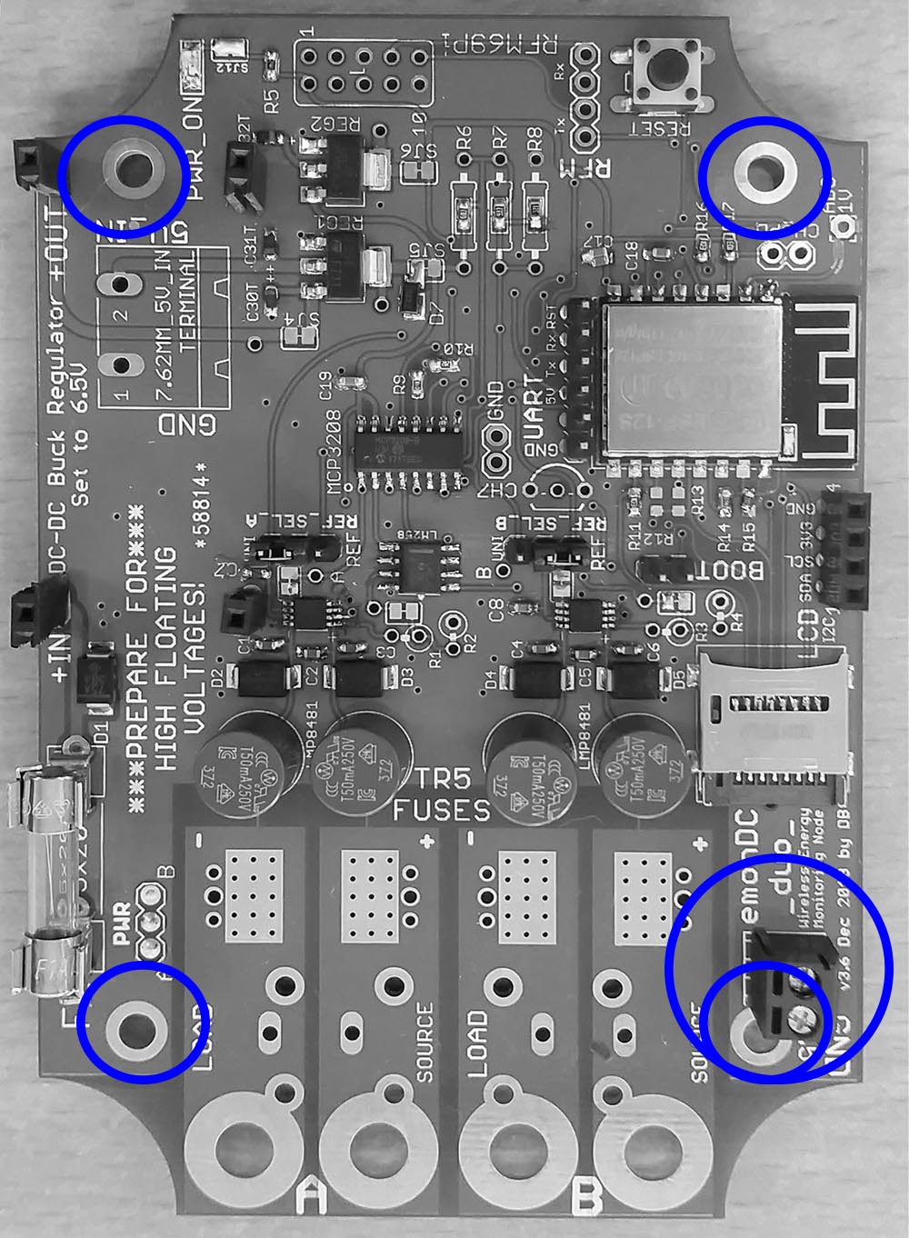
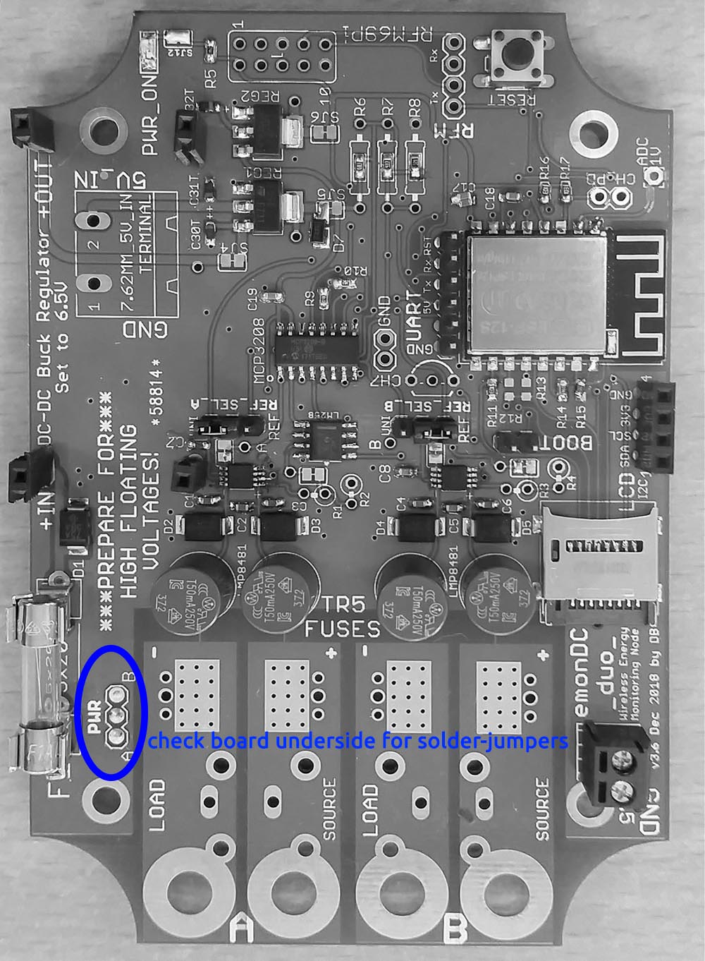
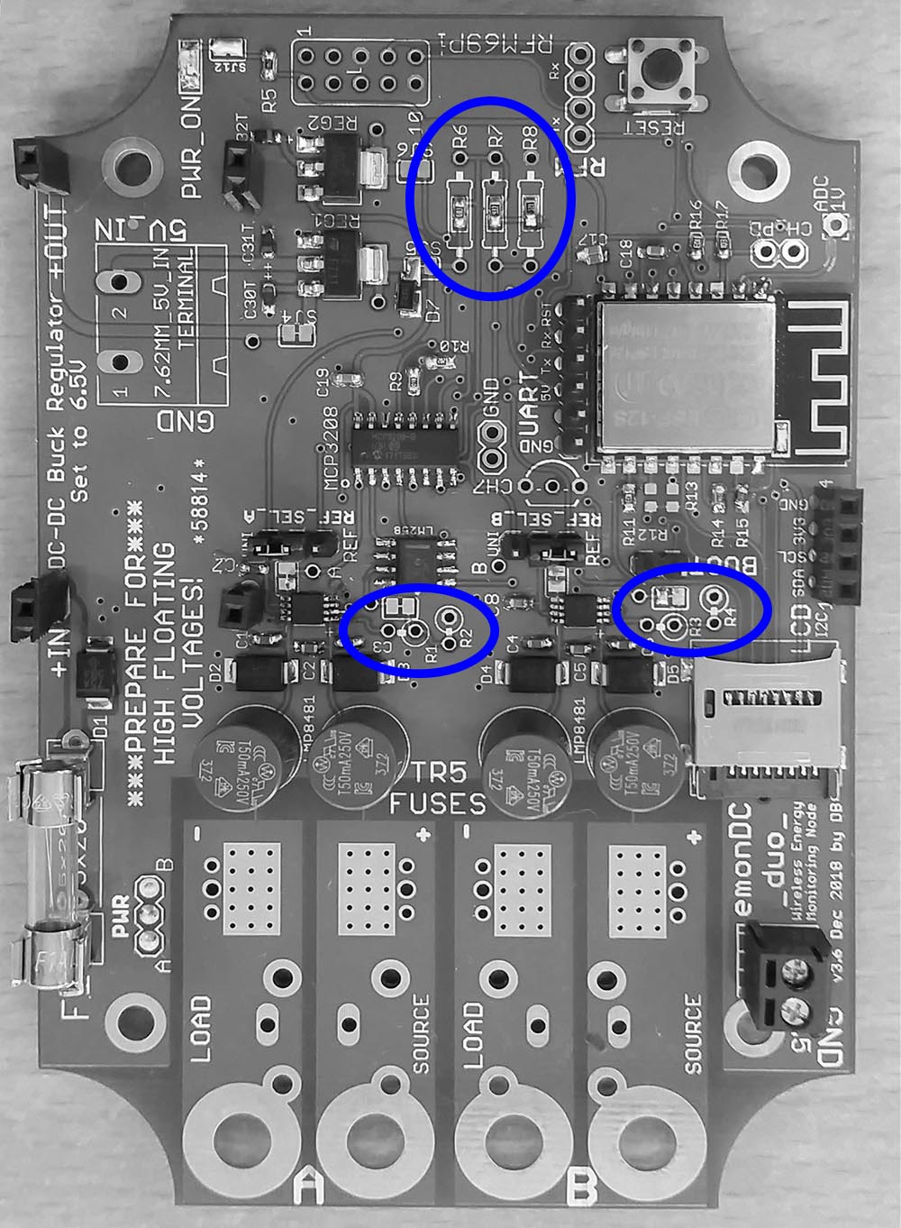
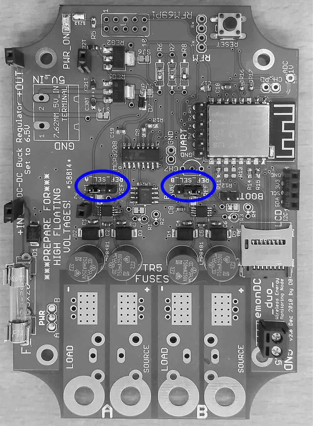
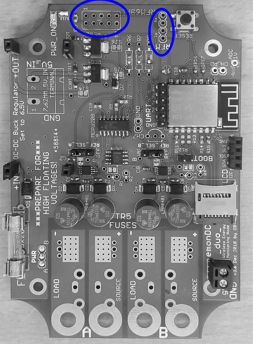
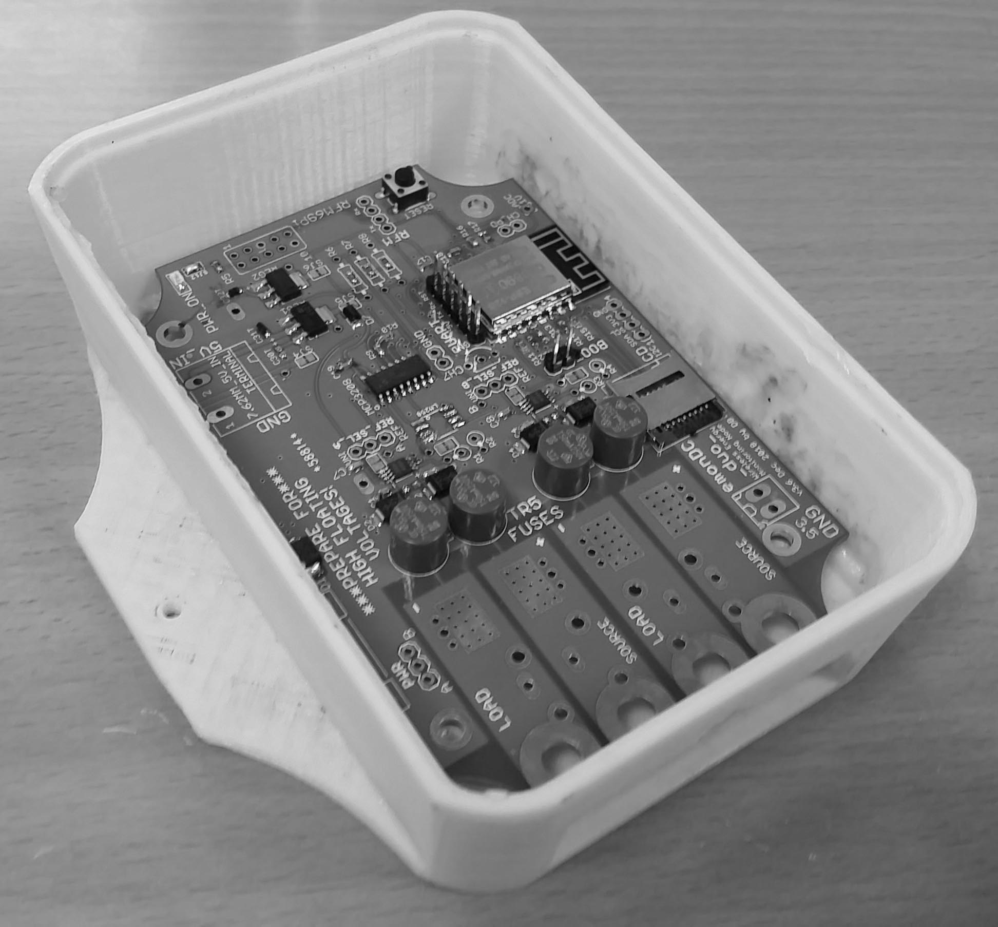
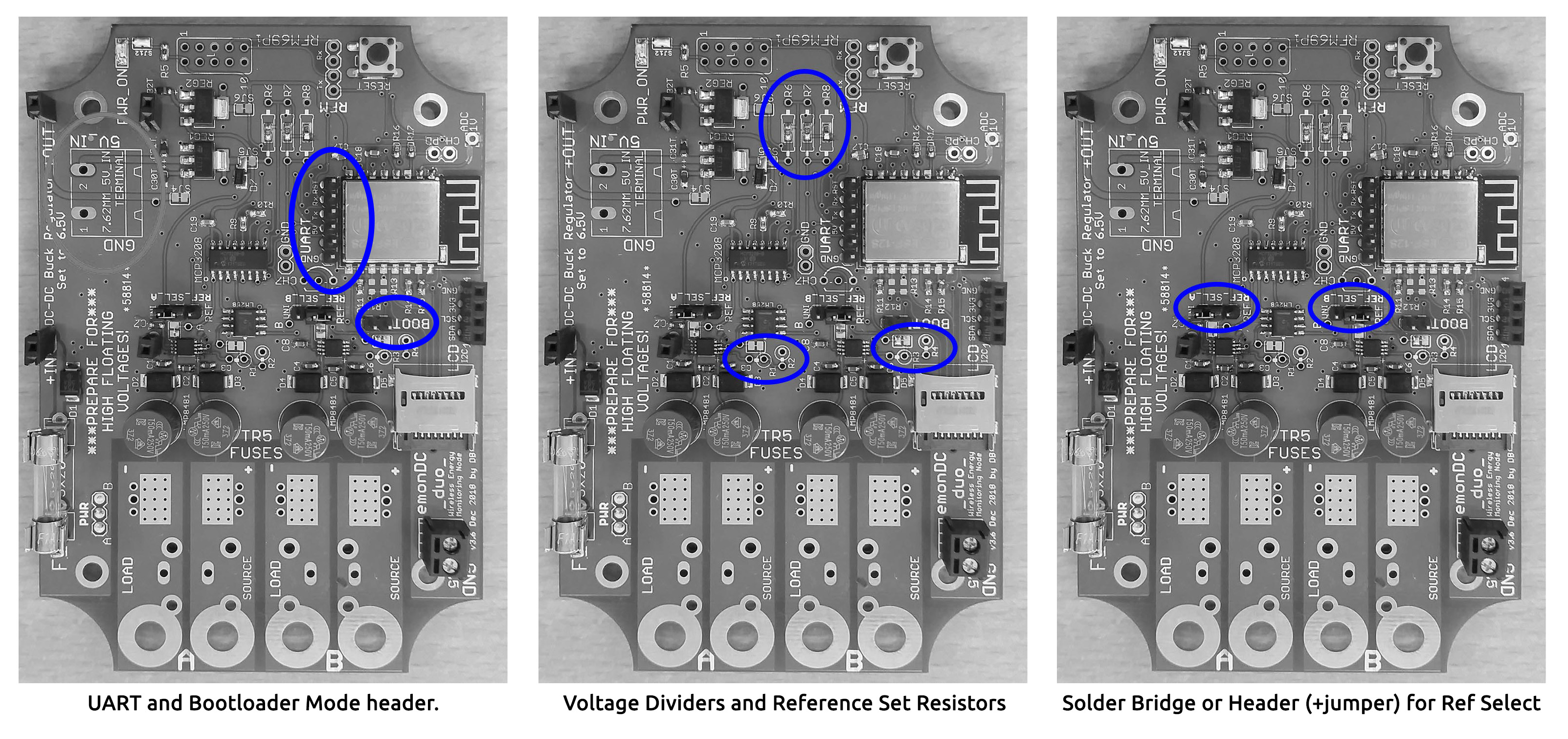
Below are a set of images outlining some other customisations.
- GND connections, for the power-supply earth with a 4mm ring terminal on a mount. The terminal block for a gnd connection or shunt-lead shielding, if used.
- 5V input location.
- Power Select header, for bringing power into an on-board buck regulator, if used.
- Reference voltage and line voltage divider resistors.
- Shunt amplifier ‘reference select’ headers, for uni or bi-directional measurement.. Typically generator (uni-directional and battery (bi-directional).
- RFM69Pi headers.
- 3D Printed Case.
- Lightning protection using Gas Discharge Tube (GDT) (external link).
Setup Guides
Plan your cabling and equipment to allow installation of this energy monitor.
Have an understanding of shunts, high-side vs low-side shunt monitoring, and whether or not your electrical Ground needs earthing or can float.
Example 1; ‘standard’ emonDCduo with enclosure, ring terminals and on-board power supply.
Tools needed: screw driver / drill, crimper / pliers, 8mm spanner or ring socket (ring socket easier). And of course, something to cut cable and strip the plastic insulation from the ends.
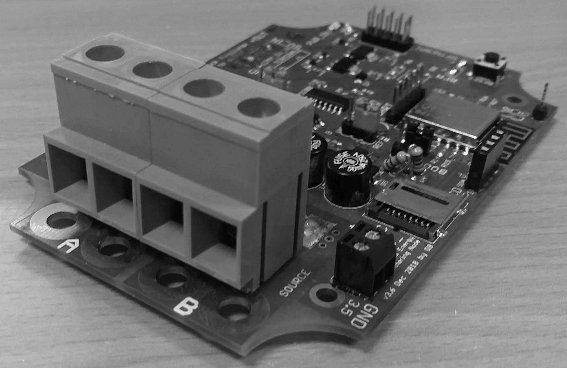
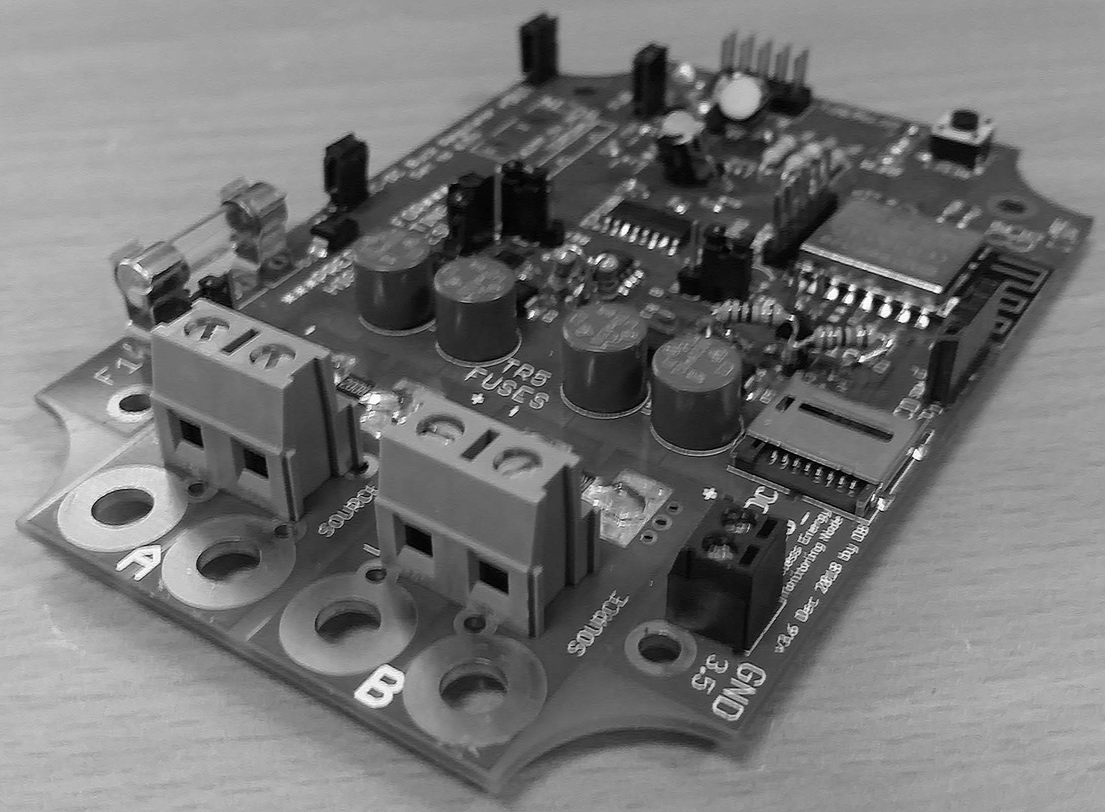
When looking at the PCB board top-side, the inputs are labelled ‘source’ and ‘load’. The source is connected to the current origin (+ive side of shunt) and the load is connected to the destination (-ive side of shunt).
- Mount enclosure, then mount PCB with bolts ready.
- Connect current-carriers, cut cables and crimp on the ring terminals.
- Power up and log in via WiFi to enter credentials and other emonESP settings.
Detailed instructions (spoiler alert!) :
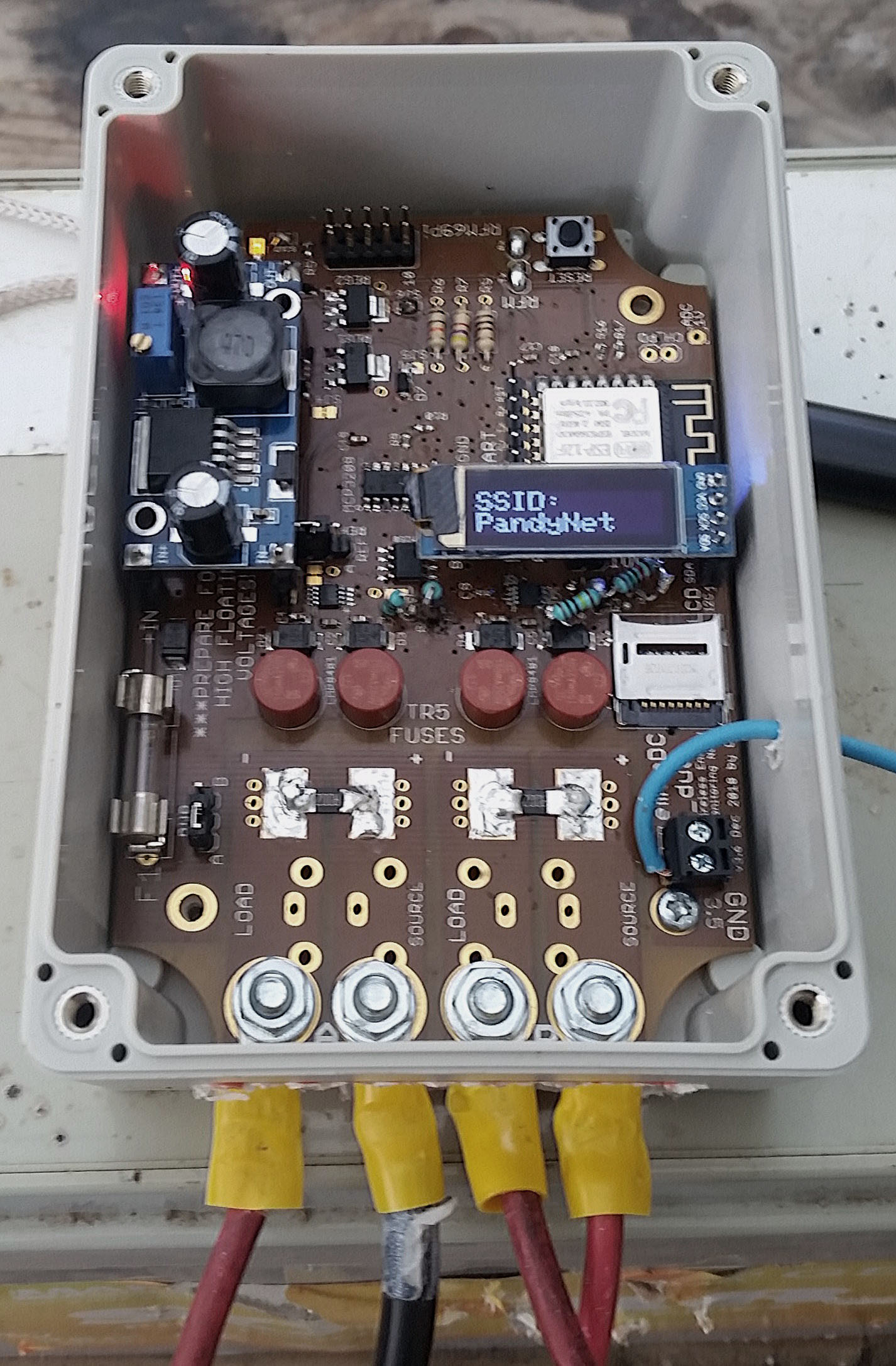
1. Purchase 'standard' board through Megni shop, select hardware options to complete purchase. 2. Take the enclosure and drill out access according to [this diagram]() (pre-drilled available from shop). 3. Select a location near the current carrying cables and mount the empty enclosure, screwing or bolting it to a surface. 4. You need two M5 bolts for each current channel. Put a serrated washer on each bolt, insert the bolts from the underside of the PCB, and then mount the PCB with the bolt threads showing, perhaps applying sideways pressure to the bolt to keep them from falling out. 5. Use the M3 screws provided to mount the PCB to the enclosure. 6. **Disconnect power from cables to be cut.** Make the cuts and strip 15mm from the ends. 7. With a crimping tool or pliers, crunch the ring terminals onto the copper cable ends, you should not be able to pull the cable out of the crimped end.. 8. Note the 'source' and 'load' labelling on the board, bring the ring terminals onto the bolts and place the flat washer, then fit the nut. 9. Tighten all bolts holding onto the crimp to keep it from spinning, the serrated washer will eventually grip and greatly help to make it tight. 10. Connect the earth via the terminal or a by using a small ring under a mounting screw. 11. Install buck-regulator, power up and log in to to the device by WiFi, here you can enter emoncms credentials, and other settings as found in emonESP.
Example 2; ‘minimal’ PCB, with enclosure, 5V input block, and external shunts.
Soldering required for minimal functioning shown below.
Then solder in two 5.08mm terminal blocks for the 5V and GND inputs.
Then 7.62mm terminal blocks (recommended) for connecting external shunts.
Online Support
. Find answers, post questions, or msg me directly at https://community.openenergymonitor.org/ . My username is @danbates
. Raise issues through this repo at the Issues tab.
Measurement of direct current (DC).
This is a project description but also a collection of ideas and findings. The diversity of approaches could be illustrated by these two websites:
- https://www.coolcomponents.co.uk/attopilot-voltage-and-current-sense-breakout-180a.html
- http://www.victronenergy.com/upload/documents/Datasheet-Battery-monitoring-EN.pdf
Safety
It’s often good practice to disconnect the power before working on cables even in extra-low voltage systems
Be aware of working voltages!
Be aware of available Amperage, and the possibility of strong currents even in extra-low voltage systems.
Isolation. The protection of users and connected devices from floating ground voltages in certain applications is very important. The approach at present is to make use of suitable physical isolation and warning labels. Bright warning labels stating ‘disconnect DC system before connecting UART’ or ‘ensure common ground between DC system and other devices to be connected’ or something similar, pending advice.
Secondly, short circuit protection needs to exist at different levels of the hardware design to avoid inadvertent damage to the unit, by assembly faults on part of the manufacturer (PCB and assembly) or assembler, or the user upon installation. This has been achieved by adding fuses and buffering certain inputs with resistors. The layout of the components factors into the safety significantly!
Thirdly, transient and reverse voltage protection. The TVS diodes specified seem to do a good job. I’ve taken a sparker from a cigarette lighter and shoved a few kV into the inputs while it was running. It worked just fine, after a reset.
The unit is defined as a Protected Extra-Low Voltage (PELV) device, and should be, if all goes well, CE certified for safety.
Approaches
Hall-effect DC monitoring ICs are simple and provide a degree of electrical isolation, however, they are inflexible and costly. This will certainly change in time as the technology develops.
Shunt monitoring potentially provides greater flexibility, high accuracy and cost-effectiveness, and is the route selected for emonDCduo.
-
The range of requirements in DC monitoring applications require a flexible approach because of:
a. Unidirectional vs bidirectional measurement needs.
b. Amperage ranges and associated cable cross sectional area. Current carriers in DC systems can range from 4mm2 to over 25mm2. The target measurement range has significant physical design implications.
c. Different cable dimensions require terminations suitable to their size and application (screw terminals, bolt ring terminals, soldered connections, etc.) there is no single solution.
d. Whole battery systems can be monitored with one shunt or individual cells of the system can require a multi-cell monitoring unit.
e. I also consider high humidity, marine and automotive applications, and have designed DCduo for a waterproof case.
f. A wide range of working voltages. -
When I consider cable sizes and suitable cable terminations, the design challenge of making a suitable unit for a wide current range makes it difficult to see any one PCB realistically and cost-effectively meeting ALL requirements. Unlike in many AC requirements where a different CT and burden resistor can be selected, DC demands a more targeted approach due to the different physical dimensions of suitable terminations. This possibly leads to the solution of designing several different boards according to the different requirements. I’m designed emonDCduo to be an allrounder as much as possible, with the option of external shunts for amperages up to 1000A.
The approach selected for first production has been dubbed emonDCduo, onboard shunts and pheonix connectors for external shunts ensure flexibility.
-
Given the nature of solar, wind and various DC applications there a requirement for a buck regulating supply, probably isolated. There needs to be a regulated and smooth output for powering the shunt monitor and other ICs.
-
Failsafe monitoring… Fuses between the shunt and monitor to protect from short circuit conditions. Do the fuses need monitoring?
-
High-side vs. low-side sensing… It’d be useful if this shunt monitor was capable of handling both applications, which means using a shunt monitor IC capable of high-side and low-side measurement. The device should ideally handle a wide common-mode voltage range, say up to 80V, and protection be in place for voltage over the common-mode voltage limit of the chip.
Wider Project Aims
- Education on working with installing hardware, cabling, the use of tools and various practical aspects.
- Create as flexible as possible unit. Aiming primarily at domestic solar, wind and battery applications.
- Compare hall-effect type to shunt monitor type DC measuring approaches, particularly in relation to safety, accuracy and flexibility, as the tech develops.
- Integrate wireless Tx function using RFM69Pi.
- Integrate LAN cable connectivity.
- Investigate a calibration routine.
- Review case design periodically.
- Look at the energy efficiency of different manufacturing approaches.
- Make units!
Questions…
- What’s the relationship to different amperages, cables sizes and suitable cable terminations at the device?
- How high a current can the PCB copper layer handle?
- How does heat dissipate through the PCB and how does this effect the value being monitored? Is a temperature sensor required for factoring in temperature drift?
Several spinoff boards have derived of this project, in various stages of completion, the latest being the ACS770 or 772 series hall-effect current sensor breakout board. Also, an isolated FTDI adaptor, emonDCmini targeted at single channel DC monitoring with WiFi capabilities, and an emonDC shield for Arduino pattern.
What I’m calling emonBuck is also available, as a switching buck regulator with low-voltage lockout and adjustable output. 1Amp rated, 3A for 10 seconds.
License
- Hardware licensed according to the TAPR Open Hardware Licence v1.0. Documentation free to use and change with accreditation to Daniel Bates @danbates2. https://www.tapr.org/TAPR_Open_Hardware_License_v1.0.txt
- Software licensed licensed to GNU General Public License v3. Free to use and change with accreditation to OpenEnergyMonitor.org. https://www.gnu.org/licenses/gpl.html